Loop Experiments – Antennas for the MW band DXer
| NAVEGUE NAS ONDAS CURTAS DO RÁDIO | ARTIGOS TÉCNICOS DX | ENVIE SEUS COMENTÁRIOS | PROCURE NESTE SÍTIO |
|
|
Loop Experiments – Antennas for the MW band DXer |
Loop for MW using Litz Wire
by Sarmento Campos - email: sarmento.campos@sarmento.eng.br
Some years ago, I have started
dxing on Medium Wave initially using a Beverage like antenna, called "BOG" -
Beverage Over Ground - coupled directly to an Icom R-75 using its 500 Ohms
input.
Using two ground rods, one connected into the receiver and the other one forming
the front of the antenna using at least 160 meters of insulated wire lying on
the sand of the beach pointed to Africa/Medium East, with a 500 Ohms
potentiometer between the wire and the ground rod pounded in the sand, it’s
adequate for transoceanic DX on MW.
With a little adjustment over the resistance of the potentiometer which gives
directivity forward, we can achieve some null to local stations, at the opposite
direction, making possible good catches like Botswana, Sudan, Iran, Saudi Arabia
and others.
This dxing is especially attractive during the gray line, mainly in Rio de
Janeiro sunset.
But founding a beach in Rio de Janeiro during summer timer to lay meters of wire
around is a big issue …
So I started researching for a portable antenna that could give me gain and
directivity to MW dxing using portable radios, like the old fashioned Sony ICF-2010.
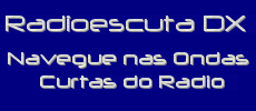
Air Core Loop for MW - 100 cm (39 inches) side length of the square with Litz
wire coil
The natural answer to this demand is the loop antenna, and that is the start of
using and developing air core loops for MW, initially with magnetic coupling to
the internal ferrite bar of the portable receiver, then, using a preamp but also
magnetic coupling to the loop into receivers like Icom R75 which do not have
internal ferrite bar antenna.
Basically there are two different types of loop antennas, one is the ferrite bar
(which will be covered in another article), and the other is wound on an air
core form like a square. One of the main features of the loop antenna is to be
very directional. The pickup pattern is shaped like a figure “8”. So, the loop
will allow signals on opposite sides to be received, but at the same time off
the sides of the loop the signal will be attenuated or even be nulled out. The
nulling feature will allow us to silence a station on a frequency and pick up
another one on the same frequency by nulling the unwanted signal.
As a rule of thumb, the larger the loop the more gain it produces. To be effective, a loop antenna needs to be able to rotate to null out a station which is obviously not possible with long wires or Beverages or its variations.
My first air core loop was made
of wood, with the square format, 60 cm length (23 inches). Using enameled wire (magnetic
solid wire of 23 AWG) and an ALPS variable capacitor (made in Japan), it covered
the entire MW band – including the X-band – 530 to 1700 kHz. Using both Sony ICF-2010
and a Grundig YB400 PE, gave me lots of loggings some transoceanic, like Saudi
Arabia, 1512 kHz, France Info, 1557 kHz, and Caribbean 530/1610 kHz.
But I thought it was not enough since I’m infected with the RF virus…
I think I could reach more signal and null capacity using more area for the loop
itself, and raise the Q factor to make it more selective.
But before assembling a new and bigger square loop I tried to wind the loop DZ-60
(*) with Litz wire just to see if should be a difference on its behavior.
In theory, the coil Wire should be litz wire made up of multiple strands of thin
wire insulated from each other. Not only less skin effect and higher Q, but
lower parasitic capacitance is to be expected in the inductor of the loop.
And after have done it at the first try a good surprise!
Using the same ALPS variable capacitor (20-365 pf) and the exactly dimensions
and the same number of turns of the winding, it’s range became wider, starting
at +- 480 kHz up to 1800 kHz.
The broader ranger of the loop antenna using Litz wire is caused by the lower
parasitic capacitance produced by the coil itself.
I cannot assure if it provides more signal level, but for sure it is more
selective and seems to be capable of nulling better not only adjacent
frequencies but especially at the same channel. The tuning process is more
critical, so a milimetric touch on the knob makes possible to catch a weak
station between two channels. Imagine two big power houses in 830 and 850 kHz,
and a distant station squeezed in 840 kHz, with Litz wire, it’s an easier job.
I am really not concerned to find out the best Litz wire configuration, I mean, my
main objective was not to measure the skin effect, or compare both signal level
(comparing to the standard solid magnetic wire) but to verify the main pratical
differences.
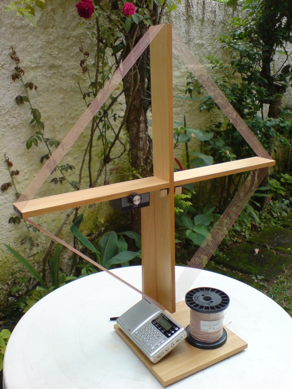
Detail of Litz wire used
For instance, the Litz wire used is made of 22 x 38 AWG which is equivalent to
24 AWG solid wire. It is far from the ideal to cover the MW band but was the
available wire to this experimentation. I also have tested 40 x 37 AWG but
pratical results looked like similar.
So I assembled a new air core loop using plywood (light weight and well finished)
but with 80 cm length (31 inches). But instead of using the magnetic wire, I
tried again the same Litz wire.
The results: simply impressive!
No lab measurements needed to observe more gain – according to the bigger area
of the loop – less turns (Loop 60 uses 17 turn, 80 uses 14) to achieve same
total inductance using the same ALPS variable capacitor.
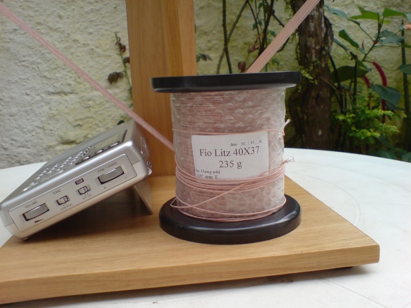
Detailed view of the coil for MW
My first experience showed that results for MW dxing with this loop compared to
the original one with magnetic fire and now with even more winding area are very
impressive.
Although I have spent more time on testing the proceedings to tune the band in
sequence (starting at the 530 up to the end of the band), I’ve found out that
neither channel was quiet, at least, a carrier was able to be heard, not even
just background noise.
I have used the following formula to calculate the loop impedance with good precision:
Groover equation for air core loop
According to the shape, I have to use the constants in the formula bellow:
The variables:
LµH – loop inductance in microhenry
A – side length in centimeters
B – length of coil (deep) in centimeters
N – number of turns (coil)
K1, K2, K3 e K4 constants related to the shape of the loop
Ln - log Nepper
Considering the fact that we have to use a variable capacitor of a know value,
and considering the intention to cover the entire MW band ( that is really broad
for any loop antenna ), you have to make a coil with the proper number of turns
that will be directly dependent of the capacitance available.
So, first, calculate L, then considering the initial frequency of 520 kHz – for
instance – and 1.710 kHz for the upper end, you will have two resonant
frequencies, F1 and F2. If you want to know the real capacitance value needed to
cover the entire range, you have to extract both capacitor values (for F1 and
F2) from the Frequency formula.
But it´s not really necessary, because most of variable capacitors have the
range of capacitance at least 20 pf and ending at least at 365 pf, it´s just the
exact value to cover the entire range.
If you use a variable capacitor with greater capacitance, no problem, I will
have the lowest frequencies lowered, but be careful, that if the initial
capacitance is more than 20 pf, let´s suppose it starts on 30 or 40 pf, the
higher frequency covered will be lower too. In practical terms, instead of
starting tuning at 520 kHz, it will cover up to let me guess, +- 480 kHz, and
instead of tuning up to 1.710 kHz, it will end up at 1.620 kHz, for example.
The simple way to solve it, is make a coil with less turns, generally, instead
of 14 turn to a 80 cm length, use 13 that will give you the entire range again.
The higher number of turns, bigger inductance, less resonant frequency. The
higher capacitance will lead to lower frequency; the lower capacitance the
resonant frequency will arise.
I have been using a commercial variable capacitor of 20 pf – 365 pf manufactured
by ALPS Japan that is the exact value to cover the entire MW band. I also have
used a Russian variable capacitor which value is 40 pf – 480 pf and then, I use
one turn less for the winding than the ALPS capacitor.
This approach is so practical that its really not necessary to make all
calculations to achieve proper results, just give 14 turns spaced approximately
7 mm each, to make the coil side 7 cm length.
I have used a little box to install and protect from dust the variable
capacitor, direct attached to the wood, with two little screws. Try to find out
the initial and the final frequency always with at least one turn than estimated
or calculated, if the range is lower ( lower than 1.710 kHz ), just decrease one
turn. It will make it resonant at higher frequency!
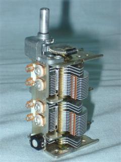
Variable capacitor - ALPS made in Japan 20pf-365pf
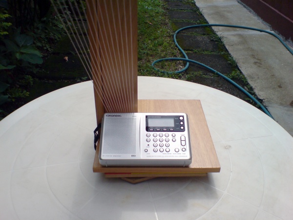
One relevant note is the quality of the Grundig YB400 PE to MW dxing. I have
been using the Sony ICF-2010 and Sony ICF-SW77 for a long time, but, even tough
the sync-AM of the ICF-2010 is no doubt the cream de la cream for a portable
device, the Grundig YB400 is a must on MW.
Excellent selectivity using its narrow filter, better image rejection and high
sensitivity, and together with good output audio, makes it a winner for MW
dxing.
I have started considering it a real contender in MW dxing when at late night I
turned on the radio when almost sleeping on my bed, when I listened to French
music very clear and loud in 1557 kHz (France Info), and then, astonished, I
have tried other frequencies like 530 kHz (Vision Cristiana) and voilá! Good
transoceanic signals just with the internal ferrite antenna. I have tried the
Sony ICF-7600G and … nothing.
Now, my main antenna is this Loop Square-100 Litz, and next try, will be to use
it with the Icom R75 using a preamp with magnetic coupling.
Keep on tuned!
Argentina MW Station 1620 kHz with local signal with the loop antenna
(*) The “DZ” is due to Denis Zoqbi, from São Paulo, who was the first to provide me this model, 60 refers to 60 cm side length of the frame. To know more about this antenna and all calculations involved click here.
The ARRL Antena Book
Joe's Carr Loop Antena
Handbook
|
|
Sitio dedicado ao Rádio
de Ondas Curtas e a prática DX -
Navegue nas Ondas Curtas do Rádio |
Acessos desde 2002